2.4.4 Modeling of nonlinear oscillations
Let us study an oscillating cantilever behavior near a sample surface. Presented below is an interactive Flash model that allows to investigate changes in the character of resonance and approach-retraction curves depending on the driving force amplitude and probe-sample distance.
Modeling of interaction force.

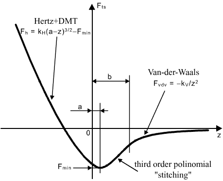
Fig. 1. The interaction force between probe and sample.
The interaction force is modeled as follows (Fig. 1):

(1)
which means that just near the sample surface the force is obtained from the Herz model taking into account the adhesion in accordance with DMT model (adhesive interaction is determined by parameter
 ). Far enough from the surface, the Van der Waals forces dominate. Then, to join the solution, the interaction force between these regions is approximated by the third-order polynomial whose coefficients are dependent on parameters
 .
.
Calculation of the cantilever parameters.

Fig. 2. Schematic geometry of cantilever.
It is assumed that the rectangular cantilever (Fig. 2) with the following sizes:
 – beam length,
 – width,
 – thickness,
 – length of the tip, is used in this model. In accordance with the theory (see (12) in chapter 2.1.2) the cantilever stiffness is given by

Calculation of curves.
The model permits to operate in two modes: study of resonance characteristics (AFC and PFC) and study of approach-retraction curves.
Upon setting the measuring mode of resonance characteristics at a given point above a sample, sets of equations (4), (5) in chapter 2.4.3 are solved simultaneously (Fig. 3). The obtained curves shape depends much on the driving amplitude. To observe a nonlinear effects (bistability and hysteresis) the cantilever stiffness should be minimum while system Q-factor and driving amplitude should be maximum. Also it is neccesary to choose probe-sample distance short. Otherwise interaction force will be neglect and not affect on resonance characteristics.

Fig. 3. Screen shot of the flash application. Example of the amplitude-frequency
characteristic calculation.
Upon setting the measuring mode of approach-retraction curves, calculation of oscillations amplitude, resonance frequency (when maximum amplitude is reached) and phase as a function of the probe-sample distance in a given range is performed according to formulas (6), (8), (12) in chapter 2.4.3. When several solutions correspond to a certain tip position, small arrows show (Fig. 4) what curve will be measured at given scan direction (approach or retraction). Recomendation of parameters choice to obtain nonlinear effects is the same as in case of resonance characteristic.

Fig. 4. Screen shot of the flash application. Example of the amplitude-distance curve
(approach-retraction curve) calculation.


