Atomic Force Microscope for Research & Education
Ask an Expert


Atomic Force Microscope for Research & Education
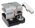
AFM holds a strong positions in scientific research as is used as a routine analytical tool for physical properties characterization with high spatial resolution down to atomic level. Solver Nano is the best choice for scientists who are need a single instrument that is an affordable, robust, user-friendly and professional tool.
Solver Nano - AFM for science.
Solver Nano is designed by the NT-MDT SI team that also created High Performance Systems like NTEGRA, NEXT II and NTEGRA Spectra II which have been proven in the scientific community through many key publications.
Solver Nano is equipped with a professional 100 micron CL (closed loop XYZ) piezotube scanner with low noise capacitance sensors. Capacitance sensors in comparison with strain gauge and optical sensors have lower noise and higher speed in the feedback signal. The CL scanner is controlled by a professional workstation and software.
These capabilities enable all of the basic AFM techniques in compact SPM design.
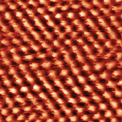
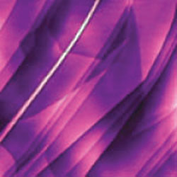
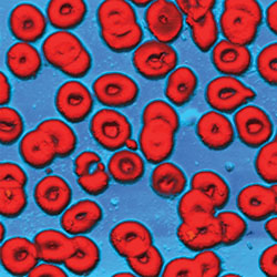
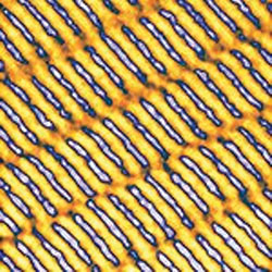
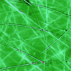
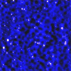
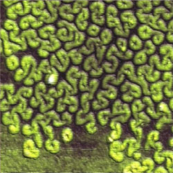
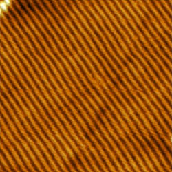
Because the SolverNano can be employed in diverse areas of research as AFM tool, several research examples are shown below:
Configuration and experimental setup:
The functionality of SOLVER Nano significantly increases due to the use of various options:
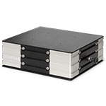
Heating stage
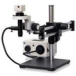
External 500x optical microscope
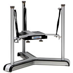
Bangee cord isolation system
Vibration isolation system.
Active damping 1-200 Hz
HybriDTMAFM technique
Contact AFM
Constant Height mode
Constant Force mode
Contact Error mode
Lateral Force Imaging
Spreading Resistance Imaging
Force Modulation Microscopy
Piezoresponse Force Microscopy
Amplitude modulation AFM,
Attractive & Repulsive regimes
Relief Imaging
Phase Imaging mode
Error mode
Electrostatic Force Mikroscopy
Scanning Capacitance Force Microscopy
Kelvin Probe Force Microscopy
Magnetic Force Microscopy
AFM Spectroscopies
Force-distance curves
Adhesion Force imaging
Amplitude-distance curves
Phase-distance curves
Frequency-distance curves
Full-resonance Spectroscopy
STM techniques
Constant Current mode
Constant Height mode
Barrier Height imaging
Density of States imaging
I(z) Spectroscopy
I(V) Spectroscopy
Lithographies
АAFM Oxidation Lithography
STM Lithography
AFM Lithography - Scratching
AFM Lithography - Dynamic Plowing
| Scanner | 100 x 100 x 12 um closed loop scanner, 3x3x3 um open loop scanner |
| AFM resolution | 0.01 nm |
| Environments | Air and liquid measurements. |
| Combined video optical microscopes |
Build in 100x optical USB microscope
External 500x optical microscope
|
| Design | Table-top, affordable, robust and user-friendly |
| Scanner | |
| Scanning field | High voltage regime: 100x100x12 um Low voltage regime: 3x3x3 um |
| Scanner type | Metrological piezotube XYZ scanner with sensors |
| Sensors type | XYZ – ultrafast capacitance sensors |
| Sensors noise | Low noise XY sensor: <0.3 nm Metrological Z sensor: <0.03 nm |
| Sensors linearity | Metrological XY sensor: <0.1% Metrological Z sensor: <0.1% |
| Overall scanner parameters | 100x100x12 um with CL Resolution: XY - 0.3 nm, Z - 0.03 nm Linearity: XY - <0.1%, Z - <0.1% 3x3x3 um with OL. Resolution: XY - 0.05 nm, Z - 0.01 nm |
| Sample | |
| Sample positioning range | 12 mm |
| Sample positioning resolution | 1.5 um |
| Sample dimension | up to 1,5” X 1,5” X 1/2”, 35x35x12 mm |
| Sample weight | up to 100 g |
| Approach system type | Z – Stepper Motor |
| Approach system step size | 230 nm |
| Approach system speed rate | 10 mm per min |
| Algorithm Gentle approach | Available (probe guaranteed to stop before it touches the sample) |
| Scanning Heads | |
| AFM head for Si cantilever | Available. All commercial cantilevers can be used |
| Type of cantilever detection | Laser/Detector Alignment |
| Probe holders | Probe holder for air measurements. Probe holder for liquid measurements. |
| Type of AFM head mounting | Cinematically mount. Mount accuracy 150 nm (Remove/mount accuracy) |
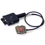
| STM AFM head for wire probes | Available. Tungsten wire for AFM measurement. (low cost experiments) Pt|Ir wire for STM measurements |
| Type of cantilever detection | Piezo for AFM measurement |
| Probe holders | Probe holder for air and liquid measurements |
| Controllers. Digital professional controller | |
| Number of images can be acquired during one scanning cycle | Up to 16 |
| Image size | Up to 8Kx8K scan size |
| ADC | 500 kHz 16-bit ADC 12 channels (5 channels with software controlling gain amplifiers 1,10,100,1000) Individual filter on each channel |
| DSP | Floating point 320 MHz DSP |
| Digital FB | Yes 6 Channels |
| DACs: | 4 composite DACs (24bit) for X,Y,Z, Bias Voltage 2 16-bit DAC for user output |
| XYZ scanner control voltage | High-voltage outputs: X, -X, Y, -Y, Z, -Z at -150 V to +150 V Low-voltage mode XY ± 10 V |
| XY RMS noise in 1000 Hz bandwidth | 0.3 ppm RMS |
| Z RMS noise in 1000 Hz bandwidth | 0.3 ppm RMS |
| XY bandwidth | 4 kHz (LV regime – 10 kHz) |
| Z bandwidth | 9 kHz |
| Maximal current of XY amplifiers | 1.5 mA |
| Maximal current of Z amplifiers | 8 mA |
| Integrated demodulator for X,Y,Z capacitive capacitance sensors | Yes |
| Open/Closed-loop mode for X,Y controlх | Yes |
| Generator frequency setting range | DC – 5 MHz |
| Deflection registration channel bandwidth | 170 Hz - 5 MHz |
| Lateral Force registration channel bandwidth | 170 Hz - 5 MHz |
| 2 additional registration channel bandwidth | 170 Hz - 5 MHz |
| Bias Voltage | ± 10 V bandwidth 0 – 5 MHz |
| Modulating signals supply | To the probe (external output); High-voltage X,Y, Z channels (including LV regime); Bias Voltage |
| Number of generators for modulation, user accessible | 2, 0-5 MHz, 0.1 Hz resolution |
| Stepper motor control outputs | Two 16-bit DACs, 20 V peak-to-peak, max current 130 mA |
| Additional digital inputs/ outputs | 6 |
| Additional digital outputs | 1 |
| I2C bus | Yes |
| Macro language | |
| Max. cable length between the controller and SPM base or measuring heads | 2 m |
| Computer interface | USB 2.0 |
| Voltage supply | 110/220 V |
| Power consumption | ≤ 110 W |
Undergraduate student manual