


2.1.4 Deflections under the transverse force
In this section we determine the magnitude and direction of the deformation produced by the transverse force
 . Solution to this problem will give the first column of tensor
 (see (2) in chapter 2.1.1) components.

(1)

(2)

(3)
As a result of the transverse force action, the complicated deformation is induced which is a superposition of simple bending and twisting (Fig. 1a и 1b).
Fig. 1a. Simple bending.
Fig. 1b. Torsion.
It is easy to obtain the inverse stiffness of simple bending (Fig.1a). This deformation is analogous to the vertical bending of z-type (Fig. 1 in chapter 2.1.2) with the only difference that in final expression for the inverse stiffness (see (12) in chapter 2.1.2) we must interchange the beam width with its thickness (
 ):
):
(4)
The solution to the problem of the rectangular beam torsion is much more complicated. Therefore, we give the formula relating the torsion angle
 and applied to the beam end force moment
 without derivation [1]:

(5)
where
 – shear modulus.
If the lateral force
acts on the tip having length
 then torque is given by
 . The tip lateral deflection is, in turn, related with the torsion angle as
 . Hence, the inverse stiffness coefficient reads:
(6)
Knowing that
 , the Poisson's ratio is
 (for the majority of materials) and taking into account the expression for
 (see (12) in chapter 2.1.2), the coefficient is calculated as:
(7)
To find the resulting tip deflection at superposition of simple bending and torsion it is just enough to sum the corresponding deflections (assuming that deformations are small):

(8)
Thus, the resulting inverse stiffness is a sum of the simple bending and torsion inverse stiffness, too:
(9)
Note that for the most of cantilevers the simple bending inverse stiffness
 (4) exceeds much the torsion inverse stiffness
 (6) so normally the simple bending can be neglected. For the standard AFM cantilever CSC12 having the following parameters:
 ,
,
 ,
,
 ,
, stiffness , the lateral stiffness constants are:
,
, stiffness , the lateral stiffness constants are:
(10)
Notice that besides the
 deflection, both the simple bending and torsion induce the deformations
 and
and
 , respectively. However, the magnitude of these displacements is of the next order of smallness as compared with
and their relation with applied force is nonlinear (quadratic), i.e. "non-Hookean". We can prove this, e.g. for torsion.
, respectively. However, the magnitude of these displacements is of the next order of smallness as compared with
and their relation with applied force is nonlinear (quadratic), i.e. "non-Hookean". We can prove this, e.g. for torsion.
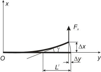
Fig. 2. On calculating
 .
.
Referring to Fig. 2, we can write
(11)
while:

(12)
Since
 , then
 . Similarly, at the simple bending
 . Hence, we can suppose

(13)
Finally, we calculate the components of the matrix (3) from chapter 2.1.1 first column. The normal to the top surface of the cantilever, subjected to the transverse force
, deflects in the
 plane, so from (11–13) we can derive:

(14)
Accordingly, there is no deflection in the
 direction, so:

(15)
Note that nonzero angle
arises only from the torsional deformation. At the simple bending the cantilever surface remains horizontal so this bending can not be detected and its magnitude can only be calculated. However, to determine the transverse force
experimentally, it is enough to detect the torsional deformation.
Summary.
- The transverse force results in a complicated deformation which is a superpositon of the simple bending and torsion of the cantilever beam. The simple bending is analogous to the z-type deflection. Solution to the more difficult problem of the rectangular beam torsion is given in literature [1].
- Only transverse deflection of the cantilever tip (in the first order of smallness according to the Hooke's law) occurs as a result of the transverse force action.
- The optical detection system registers only torsional deformation
 .
The simple bending can not be measured directly.
.
The simple bending can not be measured directly.
References.
- Feodosev V.I. Strength of Materials, MSTU publishing, 2000 – 392 p. (in Russian)