


2.1.1 The Hooke's law
The cantilever is the most common sensor of the force interaction in atomic force microscopy. The atomic force microscope acquires any information about a surface because of the cantilever beam mechanical deflections which are detected by an optical system. In noncontact microscopy, resonators of the tuning fork-type are frequently used. Such sensors require tracking of the resonance frequency shift upon the probe-surface interaction onset.
Normally, cantilever is a beam in the form of a rectangular parallepiped (Fig. 1a) having length
 , thickness
 (
(
 ) and width
 (
(
 ) or in the form of two beams connected at an angle (Fig. 1b) having a tip with length at its free end. Let us examine below the rectangular cantilever in detail. Its characteristic dimensions are shown in Fig. 1a. The probe's tip interacts with the surface. Assume that the point force acting from the sample is applied to the tip's apex.
Fig. 1a. Rectangular cantilever with a tip.
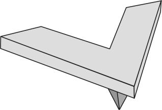
Fig. 1b. V-shaped cantilever with a tip.
The force acting on the probe has sometimes not only vertical but also horizontal components. Therefore, the cantilever tip can deflect not only along the
 -axis but in two other directions:
 and
and
 (see Fig. 1a). Let's call the force vertical component
 the normal force and longitudinal
 and transverse
 components – the lateral forces.
Because in AFM the tip-sample interaction influences the cantilever deformation, to determine the force one should know the cantilever deformation stiffness in various directions. Consider that the tip deflection vector
 (having components
 ,
,
 ,
,
 ) is linearly dependent on the applied force
 in accordance with the Hooke's law [1]:

(1)
The "constant" of proportionality is the second rank tensor
 which we call the inverse stiffness tensor. It contains all the information about elastic properties of the cantilever.
To find the components of the tensor
it is necessary to solve the problem of the cantilever static deformation under the influence of forces directed along different axes. For the sake of clarity, we write the formula (1) as a matrix expression:
(2)
Notice that the optical system detects not tip deflection but inclination of the cantilever top surface near its free end. Two angles are measured: deflection of the normal from vertical in the
 plane (angle
 ) and in the orthogonal direction – in the plane
 (angle
 ).
).
Instead of (2), we can write for the mathematical convenience the matrix expression relating angles
and
directly with force
components.
(3)
The introduced matrix, however, does not contain full information about the cantilever elastic properties in contrast to tensor
.
Summary.
- The information about a sample in AFM can be obtained only from the cantilever deformation. The optical system allows to measure two angles defining the cantilever top plane inclination.
- To determine the force acting on the cantilever one should know its elastic properties which are described by the second rank tensor of the cantilever inverse stiffness.
- The deformation-force relation is modeled by the linear Hooke's law written as the tensor expression.
References.
- Handbook of Micro/Nanotribology / Ed. by Bhushan Bharat. - 2d ed. - Boca Raton etc.: CRC press, 1999. – 859 c.