


Lateral Force Microscopy (LFM)
Application Note 074 (pdf 360 Kb)
During scanning in contact mode the cantilever bends not only along normally to the surface but also the cantilever torsional (lateral) deformation occurs. LFM measures the torsional deformation of the cantilever during scanning in contact mode (Fig. 1). The LFM image and topography can be obtained simultaneously. The lateral deformation depends on a frictional (lateral) force acting on tip [1].
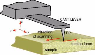
Fig. 1
The cantilever deflections are registered by optical system of microscope. The measurements of cantilever torsion are carried out with constant force condition, i.e. with constant vertical deflection of a cantilever. Therefore, it is possible to distinguish the areas with different friction (Fig. 2), in other words the LFM is sensitive to chemical composition or structure of the surface [1-3].
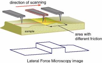
Fig. 2
If the sample surface is rough then such interpretation of the LFM image is difficult because lateral deflection is caused also by topography. The direction of scanning in LFM mode should be perpendicular to cantilever axis. This direction is X-axis for NT-MDT SI microscopes (Fig. 1).
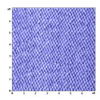
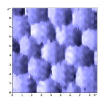
Fig. 3 demonstrate the topography (a) and signal caused by lateral deflection of cantilever (b), which were obtained simultaneously for the same area (scan 2.45x2.45 μm). The sample is the monolayer Langmuir-Blodgett (LB) film deposited on silicon surface. LB film includes the islands of two components: polymer with perfluorinated radical (‑C7F15) and diazobenzene derivative with aliphatic radical (-C18H37). The difference in height between these two components is about 1.5nm, at that higher islands correspond to diazobenzene derivative (brighter areas on topography). It is clear seen from Fig. 3b that areas correspond to different phases have different friction. LB films are too soft material for its investigations in contact mode. Despite visible surface destruction (Fig. 3a) caused by tip (semicontact mode image for this sample shows the absence of damage), the islands of both components are well resolved on submicron scale (Fig. 3b). As a result the information about chemical properties of a surface is available.
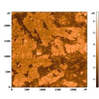
а)
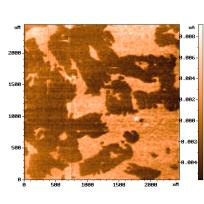
b)
Fig. 3
Fig. 3 was obtained by scanning from left to right in each scan line (the fast scanning direction). The opposite fast scanning direction (from right to left) leads to inverse image. But the scanning from left to right correctly correlates LFM signal with friction value, i.e. the LFM signal increases when friction increases. In that way the polymer with perfluorinated radical have higher friction than diazobenzene derivative. This fact corresponds to results obtained in [3].
The LFM images also helps to discern the small features of a surface. For example, the atomic resolution on mica, graphite and other flaky materials can be easy obtained by LFM with SPM produced by NT-MDT SI. Fast scanning direction for atomic resolution can be not only perpendicular to cantilever axis but also parallel to cantilever axis (Y axis for NT-MDT SI devices).
Fig. 4 shows the atomic resolution on high-oriented pyrolytic graphite (HOPG). These LFM images were obtained --> in air for scans 7nm x 7nm (Fig. 4a) and 9Åx9Å (Fig. 4b). Fast scanning direction is Y for both images.
а)
b)
Fig. 4
REFERENCES
- J. Colchero, H. Bielefeldt, A. Ruf, M. Hipp, O. Marti, and J. Mlynek, Scanning Force and Friction Microscopy, Phys. Stat. Sol. (a), 131, 1992, 73-75.
- S.N. Magonov, M.-H. Whangbo, Surface analysis with STM and AFM, VCH, Weinheim, 1996, 323p.
- R.M. Overney, E. Meyer, J. Frommer, D. Brodbeck, R. Lьthi, L. Howald, H.-J. Gьntherodt, M. Fujihira, H. Takano, Y. Gotoh, Friction measurements on phase-separated thin films with a modified atomic force microscope, Nature, 359, 1992, 133-134.