


Magnetic Force Microscopy (MFM)
Application Note 075 (pdf 220 Kb)
Magnetic-force microscopy (MFM) is effective tool to magnetic investigations on submicron scale. Image obtained by MFM is the space distribution of some parameter characterizing magnetic probe-sample interaction, i.e. interaction force, amplitude of vibrating magnetic probe etc. The magnetic probe is standard silicon cantilever (or silicon nitride cantilever) coated by magnetic thin film. MFM measurements are available with every SPM produced by NT-MDT SI and enable to high resolution investigate magnetic domain structure, reading and recording information in magnetic media, magnetization reversal processes etc.
A most important problem in MFM is the separation the magnetic image from the topography. To solve this problem the magnetic measurements with NT-MDT SI SPMs are executed by means of two-pass method [1, 2]. In the first pass the topography is determined in contact or semicontact mode. In the second pass the cantilever is lifted to a selected height for each scan line (or after topography measurement), and scanned using the stored topography (without the feedback). As a result the tip-sample separation during second pass is kept constant (Fig.1). This tip-sample separation must be large enough to eliminate the Van der Waals' force. During second pass the short-range Van der Waals' force vanishes and the cantilever is affected by long-range magnetic force. Both the height-image and the magnetic image are obtained simultaneously with this method.
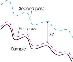
Fig.1
In the second pass two methods are available:
1. DC MFM. This MFM mode detects the deflection (DFL) of a nonvibrating cantilever due to the magnetic interaction between the tip and the sample (similar contact mode) [3]. The magnetic force acting on the cantilever can be obtained by multiplying the deflection of the cantilever by the cantilever force constant. Due to a small size of the magnetic cantilever it is possible to consider it as a point magnetic dipole. In this approximation the force acting on the cantilever during the second pass can be written in the form [4, 5]:
 , (1)
, (1)
where  is the effective magnetic moment of the cantilever,
  is the stray field from the sample. The equation (1) is the Zeeman energy derivative taken with the inverse sign.
2. AC MFM. During second pass the cantilever resonance oscillations can be used to detect the magnetic force data (just as in the semiconact mode). In this mode the microscope detects the force derivative [4, 5].
It is possible to record the following signals in the AC MFM for the magnetic image mapping:
a) The amplitude of cantilever oscillations [4, 5, 6].
b) The phase shift between vibrations of the piezoelectric actuator and the cantilever.
The first method (DC MFM) is usually used to detect the magnetic fields, which are strong enough, for example the stray field from magnetic recording head [3] or the stray field of permanent magnets. The AC MFM methods are more sensitive.

а)
b)
c)
d)
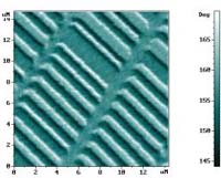
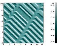
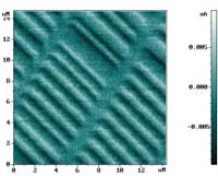
Fig. 2 Hard disk. a) topography; b), c), d) are MFM images: b) phase shift , c) amplitude shift (second pass), d) deflection of the cantilever (third pass).
Fig. 2 demonstrates the different techniques of the MFM imaging applied to the hard disk. These images were acquired simultaneously by three passes. During second pass phase and amplitude shift of the oscillating magnetic cantilever were measured (Fig. 2b and Fig. 2c). These images were obtained with ΔZ=50 nm. Fig. 2d corresponds to the normal deflection of the nonvibrating cantilever, that was obtained during third pass with ΔZ=-5 nm. The minus sign means that the third pass was realized closer to the sample than the first one. This is possible because the semicontact mode was used for topography measurement. The amplitude of cantilever oscillations was about 40nm during first pass.
The various standard samples can be used as a test for MFM:
- Magnetic tapes, hard disks, magneto-optical disks etc. (for example [7]).
- Magnetotactic bacterium [8].
- Magnetic heads [3, 9, 10]: the strong magnetic field from magnetic head is used.
- Microwire [11]. In this case the magnetic field caused by the current in micron-size wire is detected.
Some of these samples can be used also for quantification of the MFM measurements [7, 8, 9, 10]. The metal rings, fabricated using electron-beam lithography, were used to calibrate MFM in [11]. A MFM tip's effective magnetic charge and effective magnetic moment, as well as the MFM sensitivity to the second derivative of the magnetic field (2) were determined from MFM signal of the ring at a different electric current in the ring. In this case the equations for magnetic field and its derivatives on the axis of the ring were used to MFM quantification.
The magnetic images have strong dependence on tip's properties [12]. Hard magnetic coating of the tip can affect the magnetic structure of the sample, and vice versa - sample magnetic field can reverse the magnetization of the tip. To avoid (or minimize) these reversal processes it is useful to exclude the first pass. This can be achieved by measuring without feedback. In this case the measurements are executed with constant Z-coordinate of scanner. Such method leaves out of account the slope and the topography of the sample. In spite of this disadvantage such method allows to measure soft magnetic materials more qualitatively.
One of important problems is the interpretation of magnetic image. The determination of true distribution of magnetization in the sample from MFM image is not possible in general [8]. The sample magnetization cannot be uniquely determined from a given field map. The attempts of such reconstruction were made in [10, 13].
The tips with relatively hard magnetic coating are suitable for most of the samples. The image obtained by such tips is more interpretable. Company NT-MDT SI offers two types of cantilevers with hard magnetic cobalt coatings:
- Silicon cantilevers with cobalt coating.
- Silicon whisker-type cantilevers with cobalt coating.
Whisker-type cantilevers better correspond to the point dipole approximation model and provides better resolution and interpretability. This type of cantilevers has magnetic coating only on tip due to electron-beam lithography. Such design also provides the better resolution than the first one.
REFERENCE
- Y. Martin and H.K. Wickramasinghe, Magnetic imaging by "force microscopy" with 1000-A resolution, Appl.Phys.Lett., 1987, 50(20), 1455-1457.
- Y. Martin, D. Rugar, and H.K. Wickramasinghe, High-resolution magnetic imaging of domains in Tb-Fe by force microscopy, Appl.Phys.Lett., 1988, 52(3), 244-246.
- P. Rice, J. Moreland, A. Wadas, dc magnetic force microscopy imaging of thin-film recording head, J. Appl. Phys., 1994, 75 (10), 6878-6880.
- D. Rugar, H. Mamin, P. Guethner, S. Lambert, J. Stern, I. McFadyen, and T. Yogi, Magnetic force microscopy: General principles and application to longitudinal recording media, J. Appl. Phys., 1990, 68 (3), 1169-1183.
- P. Guethner, H. Mamin, D. Rugar, Magnetic force microscopy. In book: Scanning Tunneling Microscopy II, Springer-Verlag Berlin Heidelberg, 1992. Eds: R. Wiesendanger, H.-J. Gunherodt, 151-207.
- Y. Martin, C.C. Williams, and H.K. Wickramasinghe, Atomic force microscope - force mapping and profiling on a sub 100-A scale, J. Appl. Phys.,1987, 61(10), 4723-4729.
- P. Rice, S. Russek, J. Hoinville, M. Kelley, Optimizing the NIST magnetic imaging reference sample, IEEE Trans. Magn., 1997, 33 (5), 4065-4067.
- E. Dan Dahlberg, J.-G. Zhu, Micromagnetic microscopy and modeling, Physics Today, april 1995, 34-40.
- S. Khizroev, W. Jayasekara, J. Bain, R. Jones, Jr. & M. Kryder, MFM quantification of magnetic fields generated by ultra-small single pole perpendicular heads, IEEE Trans. Magn., 1998, 34 (4), 2030-2032.
- I. Ishii, K. Mukasa, Y. Kanai, A novel numerical approach to interpret images obtained by magnetic force microscope, IEEE Trans. Magn., 1998, 34 (5), 3455-3458.
- L. Kong, S. Chou, Quantification of magnetic force microscopy using a micronscale current ring, Appl. Phys. Lett., 1997, 70 (15), 2043-2045.
- M. Al-Khafaji, W. Rainforth, M. Gibbs, J. Bishop, H. Davies, The effect of tip type and scan height on magnetic domain images obtained by MFM, IEEE Trans. Magn., 1996, 32 (5), 4138-4140.
- R. Madabhushi, R Gomez, E. Burke, I. Mayergoyz, Magnetic biasing and MFM image reconstruction, IEEE Trans. Magn., 1996, 32 (5), 4147-4149.